
Most Trending
-
 บอกเลยว่าคลำอยู่หลายชั่วโมง กว่าจะทำให้ มันแสดงผลได้ ....ตอนแรกพยายามพ่วง RTC แต่ทดลองแล้วปรากฎว่า ไม่สามารถตั้งเวลาได้เลยเอาออกก่อน .... ...
 -
 DS18B20 เป็นหนึ่งในตระกูล DS18XXX ที่ปัจจุบัน เปลี่ยนเจ้าของจาก Dallas ไปสู่ MAXIM เรียบร้อยแล้วดาต้าชีต อยู่ที่นี่ DS18B20 data sheet by MA...
 -
 ปลายๆ กุมภา 57 : กรุงเทพ อากาศร้อนใช้ได้เลย... ความชื้นสัมพัทธ์ ประมาณนี้กำลังอึดอัด เหนี่ยวเหนอะ สุดๆ (ความชื้นที่กำลังสบา...
 -
 PIR sensor กับ Arduino คำค้นใน google : arduino with pir sensor หรือ arduino pir motion sensor พิมพ์ลงไปประมาณนี้ เดี๋ยว google มันจะแน...
 -
 เผอิญจะต่อ LED กับ arduino ปรากฏว่าซื้อมาแล้ว ต่อกับบอร์ดปรากฏว่ามันไม่ติด...งง เป็นไปได้จะใด? สรุป เป็นแบบนี้ ปกติผมใช้แต่ LED ชนิด 4 ขา ม...
 -
 ออกตัวก่อนนะครับ สำหรับคนที่แวะมาเจอ blog นี้ โปรดอย่าคิดว่าผมเป็นเซียน arduino หรือ ไมโครคอนโทรลเลอร์ หรือ มีอาชีพเป็นโปรแกรมเม...
 -
 Arduino Home Energy Monitor Link ครับ http://www.desert-home.com/p/test-html-code.html http://www.joecool.org/joe_home_energy_pow...
 -
 ยำรวมกันโปรเจ็กที่เท่าไหร่ก็ไม่ทราบแล้ว ข้อควรทราบเมื่อใช้งาน Ethernet Shield WZ5100 คือ จุดต่อที่ห้ามใช้คือ pins A0, A1, D4, and D10-D...
 -
 เขียนหน้านี้สักเล็กน้อยกันลืม เกี่ยวกับไฟใช้เลี้ยงบอร์ด Pro mini และขั้วต่อ ว่ามันอยู่ตรงไหน ดูภาพประกอบ ไฟเข้าขั้วบวก-ลบสำหรับเลี...
 -
 Blog นี้ที่ทำขึ้นมา เพื่อต้องการรวบรวมข้อมูล , โครงงานที่ใช้ Arduino เป็นหลัก โดยแอดมินไล่เก็บบทความ หรือ เว็บต่างๆ ที่ไปคุ้ยๆ มาในเน็ต ข้อม...
Popular Posts
-
บอกเลยว่าคลำอยู่หลายชั่วโมง กว่าจะทำให้ มันแสดงผลได้ ....ตอนแรกพยายามพ่วง RTC แต่ทดลองแล้วปรากฎว่า ไม่สามารถตั้งเวลาได้เลยเอาออกก่อน .... ...
-
DS18B20 เป็นหนึ่งในตระกูล DS18XXX ที่ปัจจุบัน เปลี่ยนเจ้าของจาก Dallas ไปสู่ MAXIM เรียบร้อยแล้วดาต้าชีต อยู่ที่นี่ DS18B20 data sheet by MA...
-
ปลายๆ กุมภา 57 : กรุงเทพ อากาศร้อนใช้ได้เลย... ความชื้นสัมพัทธ์ ประมาณนี้กำลังอึดอัด เหนี่ยวเหนอะ สุดๆ (ความชื้นที่กำลังสบา...
-
PIR sensor กับ Arduino คำค้นใน google : arduino with pir sensor หรือ arduino pir motion sensor พิมพ์ลงไปประมาณนี้ เดี๋ยว google มันจะแน...
-
เผอิญจะต่อ LED กับ arduino ปรากฏว่าซื้อมาแล้ว ต่อกับบอร์ดปรากฏว่ามันไม่ติด...งง เป็นไปได้จะใด? สรุป เป็นแบบนี้ ปกติผมใช้แต่ LED ชนิด 4 ขา ม...
-
ออกตัวก่อนนะครับ สำหรับคนที่แวะมาเจอ blog นี้ โปรดอย่าคิดว่าผมเป็นเซียน arduino หรือ ไมโครคอนโทรลเลอร์ หรือ มีอาชีพเป็นโปรแกรมเม...
-
Arduino Home Energy Monitor Link ครับ http://www.desert-home.com/p/test-html-code.html http://www.joecool.org/joe_home_energy_pow...
-
ยำรวมกันโปรเจ็กที่เท่าไหร่ก็ไม่ทราบแล้ว ข้อควรทราบเมื่อใช้งาน Ethernet Shield WZ5100 คือ จุดต่อที่ห้ามใช้คือ pins A0, A1, D4, and D10-D...
-
เขียนหน้านี้สักเล็กน้อยกันลืม เกี่ยวกับไฟใช้เลี้ยงบอร์ด Pro mini และขั้วต่อ ว่ามันอยู่ตรงไหน ดูภาพประกอบ ไฟเข้าขั้วบวก-ลบสำหรับเลี...
-
Blog นี้ที่ทำขึ้นมา เพื่อต้องการรวบรวมข้อมูล , โครงงานที่ใช้ Arduino เป็นหลัก โดยแอดมินไล่เก็บบทความ หรือ เว็บต่างๆ ที่ไปคุ้ยๆ มาในเน็ต ข้อม...
Arduino with TFT LCD SPI interface 1.8"
บอกเลยว่าคลำอยู่หลายชั่วโมง กว่าจะทำให้ มันแสดงผลได้ ....ตอนแรกพยายามพ่วง RTC แต่ทดลองแล้วปรากฎว่า ไม่สามารถตั้งเวลาได้เลยเอาออกก่อน ....

ข้อสังเกตุของงานชิ้นนี้คือ ตัวจอ TFT 1.8 SPI มีลักษณะความแตกต่างจากจอที่ผลิตจาก Arduino หรือ Sparkfun เช่นความละเอียด , การเชื่อมต่อ, ไฟเลี้ยงจอ,รวมไปถึง Liblary ที่เอามาใช้ .. ซึ่งทดลองใช้หลายตัว จนมาจบที่ TFT.h ของ arduino เอง ซึ่งตอนแรกลองใช้ของ adafruit แล้วไม่เวิร์ก แต่ TFT.h ของ arduino มีพื้นฐานไส้ในเหมมือนกันกับของ adafruit ทำให้ใช้คำสั่งลักษณะเดียวกันได้
 |
หน้าตาจอ TFT 1.8 SPI จอมวุ่น (ขนาด 1.8 ตัวบน) |
 |
การต่อสาย |
แนะนำการซื้อ TFT ให้ดู chip บนบอร์ดว่าใช้ตัวไหน เวลาเรา search หา Liblary จะได้หาถูกตัว
code
#define sclk 13
#define mosi 11
#define cs 10
#define dc 9
#define rst 8
#include <TFT.h>
#include <SPI.h>
#include <stdio.h>
#include <dht.h>
#define DHT11_PIN 4 // DHT11 data pin is connected to Arduino pin.
dht DHT;
Adafruit_ST7735 tft = Adafruit_ST7735(cs, dc, mosi, sclk, rst);
//Black theme
#define COLOR1 ST7735_WHITE
#define COLOR2 ST7735_BLACK
//White theme
//#define COLOR1 ST7735_BLACK
//#define COLOR2 ST7735_WHITE
int text_color_humidex;
float humidity, temperature,humidex;
String message;
void setup(void) {
Serial.begin(9600);
tft.initR(INITR_BLACKTAB); // initialize a ST7735S chip, black tab
tft.fillScreen(COLOR2);
}
void loop() {
// get data from DHT22
DHT.read11(DHT11_PIN);
humidity = (DHT.humidity);
temperature = (DHT.temperature);
//humidex is calculated
humidex = calculate_humidex (temperature, humidity);
// Table
tft.drawRect(0, 0, 128, 160, COLOR1); // ตีตารางขอบรอบด้าน
tft.drawLine(0, 50, 128, 50, COLOR1); // ขีดเส้นคั่น
tft.drawLine(0, 100, 128, 100, COLOR1); //ขีดเส้นคั่น
// data is outputed
temperature_to_lcd (temperature, 4);
humidity_to_lcd (humidity, 55);
humidex_to_lcd (humidex, 105);
}
// outputs temperature to LCD
void temperature_to_lcd (float temperature, unsigned char text_position )
{
int text_color;
tft.setCursor(4,text_position);
tft.setTextColor(COLOR1,COLOR2);
tft.setTextSize(1);
tft.print("Temperature:");
tft.setTextSize(3);
if (temperature>0) {
text_color=ST7735_RED;
}
else {
text_color=ST7735_BLUE;
}
tft.setCursor(1,text_position+20);
fix_number_position(temperature);
tft.setTextColor(text_color,COLOR2);
tft.print(temperature,1);
tft.setCursor(108,text_position+20);
tft.print("C");
tft.drawChar(90,text_position+20, 247, text_color, COLOR2, 2); //degree symbol
}
//outputs humidity to LCD
void humidity_to_lcd (float humidity, unsigned char text_position )
{
tft.setTextColor(COLOR1,COLOR2);
tft.setCursor(4,text_position);
tft.setTextSize(1);
tft.println("Humidity:");
tft.setTextSize(3);
tft.setCursor(1,text_position+20);
fix_number_position(humidity);
tft.print(humidity,1);
tft.print(" %");
}
//outputs Humidex to LCD
void humidex_to_lcd (float humidex, unsigned char text_position )
{
tft.setCursor(4,text_position);
tft.setTextSize(1);
tft.println("Humidex:");
tft.setTextSize(3);
tft.setCursor(1,text_position+17);
if ((humidex >= 21 )&&(temperature < 44)) {
fix_number_position(humidex);
get_humidex_color_warning_message(humidex);
tft.setTextColor(text_color_humidex,COLOR2);
tft.print(humidex,1);
tft.setCursor(108,text_position+17);
tft.print("C");
tft.drawChar(90,text_position+17, 247, text_color_humidex, COLOR2, 2); //degree symbol
tft.setCursor(3,text_position+43);
tft.setTextSize(1);
tft.print(message);
}
else {
tft.print(" --.-");
tft.setCursor(108,text_position+17);
tft.print("C");
tft.drawChar(90,text_position+17, 247, COLOR1, COLOR2, 2); //degree symbol
tft.setCursor(1,text_position+43);
tft.setTextSize(1);
tft.println(" ");
};
}
// aligs number to constant position
void fix_number_position(float number)
{
if ((number >= -40)&&(number < -9.9))
{
;
}
if ((number >= -9.9)&&(number < 0.0))
{
tft.print(" ");
}
if ((number >= 0.0 )&&(number < 9.9))
{
tft.print(" ");
}
if ((number >= 9.9 )&&(number < 99.9))
{
tft.print(" ");
}
if ((number >= 99.9 )&&(number < 151))
{
tft.print("");
}
}
//function to calculete Humidex
float calculate_humidex(float temperature,float humidity) {
float e;
e = (6.112 * pow(10,(7.5 * temperature/(237.7 + temperature))) * humidity/100); //vapor pressure
float humidex = temperature + 0.55555555 * (e - 10.0); //humidex
return humidex;
}
// Setting text color and message based on Humidex value
void get_humidex_color_warning_message(float humidex)
{
if ((humidex >= 21 )&&(humidex < 27))
{
text_color_humidex=tft.Color565(0, 137, 0);
message= "No discomfort ";
} // dark green
if ((humidex >= 27 )&&(humidex < 35))
{
text_color_humidex=tft.Color565(76, 255, 0); // light green
message= "Some discomfort ";
}
if ((humidex >= 35 )&&(humidex < 40))
{
text_color_humidex=tft.Color565(255, 255, 0);
message= "Great discomfort ";
} // yellow
if ((humidex >= 40 )&&(humidex < 46))
{
text_color_humidex=tft.Color565(255, 140, 0);
message= "Health risk ";
} //light orange
if ((humidex >= 46 )&&(humidex < 54))
{
text_color_humidex=tft.Color565(221, 128, 0);
message= "Great health risk ";
} //dark orange
if ((humidex >= 54 ))
{
text_color_humidex=tft.Color565(255, 0, 0);
message= "Heat stroke danger ";
} // red
}
My English is not pretty good pls. forgive for all miss communicated.
Project Reference , many thanks for awesome idea : เว็บอ้างอิงโปรเจ็กนี้
temperature-and-humidityhumidex-meter
Mini-Arduino-enviroment-monitor
simple-indoor-climate-monitoring
อะไรคือ Humidex เพิ่งเคยได้ยินเหมือนกัน wiki/Humidex
อุปกรณ์ที่ใช้
1.DHT11 ข้อมูลอยู่ที่นี่ htDHTLib
2.TFT LCD ขนาด 1.8" ใช้ตามรูปเลย
วิธีการต่อ TFT_LCD_LCM_SPI_Interface#Pins
เพิ่มเติม eds-tft-lcd-lcm-spi-interface-variable1-8
เริ่มใช้Arduino TFT screen Guide TFT
Arduino UNO R3 + Ethernet Shield + PIR + MQ2 + DHT11
ยำรวมกันโปรเจ็กที่เท่าไหร่ก็ไม่ทราบแล้ว
ข้อควรทราบเมื่อใช้งาน Ethernet Shield WZ5100 คือ จุดต่อที่ห้ามใช้คือ pins A0, A1, D4, and D10-D13
ดังนั้น pin ที่เราจะใช้ได้คือ pin อื่น นอกเหนือจากที่แจ้งไว้
โปรเจ็กนี้
 |
| MQ2 gas sensor |
PIR ใช้ pin2
MQ2 ใช้ A3
จุดสังเกตุ เมื่อ PIR ตรวจเจออะไร ค่า MQ2 ที่แสดง จะแกว่งแป๊บนึง ก่อนกลับมาสู่จุดปกติ
หน้าตาใน command จะเป็นแบบนี้

CODE
#include <dht.h>
dht DHT;
#define DHT11_PIN 3 //
#define DHTTYPE DHT11
const int analogInPin = A3; // Analog input pin that the potentiometer is attached to
const int analogOutPin = 9; // choose the pin for the LED
int sensorValue = 0; // value read from the pot
int inputPin2 = 2; // choose the input pin (for PIR sensor)
int ledPin2 = 13;
int pirState = LOW; // we start, assuming no motion detected
int val = 0; // variable for reading the pin status
int pinSpeaker2 = 10; //Set up a speaker on a PWM pin (digital 9, 10, or 11)
void setup() {
Serial.begin(9600);
delay(300);//Let system settle
Serial.println("Humidity and temperature\n\n");
delay(700);//Wait rest of 1000ms recommended delay before
//accessing sensor
pinMode(analogOutPin, OUTPUT);
pinMode(ledPin2, OUTPUT); // declare LED as output
pinMode(inputPin2, INPUT); // declare sensor as input
pinMode(pinSpeaker2, OUTPUT);
Serial.begin(9600);
}
void loop(){
DHT.read11(DHT11_PIN);
Serial.print("Current humidity = ");
Serial.print(DHT.humidity);
Serial.print("% ");
Serial.print("temperature = ");
Serial.print(DHT.temperature);
Serial.println("C ");
delay(800);
val = digitalRead(inputPin2); // read input value
if (val == HIGH) { // check if the input is HIGH
digitalWrite(ledPin2, HIGH); // turn LED ON
playTone(300, 160); // เดิม 300, 160)
delay(100); // เดิม 150
if (pirState == LOW) {
// we have just turned on
Serial.println("Motion detected!");
// We only want to print on the output change, not state
pirState = HIGH;
}
} else {
digitalWrite(ledPin2, LOW); // turn LED OFF
playTone(0, 0);
delay(300);
if (pirState == HIGH){
// we have just turned of
Serial.println("Motion ended!");
// We only want to print on the output change, not state
pirState = LOW;
}
}
// read the analog in value:
sensorValue = analogRead(analogInPin);
// determine alarm status
if (sensorValue >=750)
{
digitalWrite(analogOutPin, HIGH); // sets the LED on
}
else
{
digitalWrite(analogOutPin, LOW); // sets the LED off
}
// print the results to the serial monitor:
Serial.print("sensor = " );
Serial.println(sensorValue);
// wait 10 milliseconds before the next loop
// for the analog-to-digital converter to settle
// after the last reading:
delay(10);
}
// duration in mSecs, frequency in hertz
void playTone(long duration, int freq) {
duration *= 1000;
int period = (1.0 / freq) * 1000000;
long elapsed_time = 500; // เดิม 0
while (elapsed_time < duration) {
digitalWrite(pinSpeaker2,HIGH);
delayMicroseconds(period / 2);
digitalWrite(pinSpeaker2, LOW);
delayMicroseconds(period / 2);
elapsed_time += (period);
}
}
Arduino ทดสอบ LD1117 , Ethernet module ENC28J60
draft บทความก่อนโพส
1. การทดลองใช้ LD1117 เพื่อลดแรงดันปลายทางให้เหลือ 3.3V ต้นทางจากเว็บนี้ LD1117-voltage-regulators Read from Arduino
2. การทดลองใช้ Ethernet module ENC28J60
1. การทดลองใช้ LD1117 เพื่อลดแรงดันปลายทางให้เหลือ 3.3V ต้นทางจากเว็บนี้ LD1117-voltage-regulators Read from Arduino
2. การทดลองใช้ Ethernet module ENC28J60
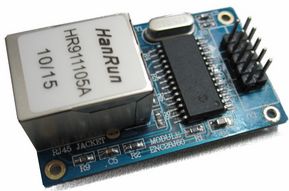
บทความ ENC28J60 Ethernet module
ไลบราลี่ มีหลายตัว ลองโหลดมาใช้ดู https://github.com/jcw/ethercard
Arduino + IR Receiver Module การใช้สารพัด Remote ควบคุมอุปกรณ์โดยผ่าน Arduino
Blog นี้ที่ทำขึ้นมา เพื่อต้องการรวบรวมข้อมูล , โครงงานที่ใช้ Arduino เป็นหลัก โดยแอดมินไล่เก็บบทความ หรือ เว็บต่างๆ ที่ไปคุ้ยๆ มาในเน็ต ข้อมูลส่วนใหญ่เป็นภาษาอังกฤษ แต่ไม่ยาก มั่วๆ ไล่ๆ วงจรก็พอได้
เก็บๆ รวบรวมไว้ก่อน เอาไว้อ่านย้อนเอาทีหลังตอนว่างๆ ใครสนใจเรื่อง arduino มาโพสแลกเปลี่ยนความรู้กันได้นะครับ
ตอนนี้จะเกี่ยวกับการใช้ arduino ในการอ่านโค้ดที่รับมาจากรีโมทคอนโทรล ส่วนจะใช้รีโมทอะไร ส่วนใหญ่ในเว็บจะทดลองโดยใช้รีโมททีวี เป็นหลัก ดังนั้นถ้าเราไม่อยากคลำมาก ก็ใช้รีโมททีวีตามเขาไป สะดวกดี ส่วนยี่ห้อไหนก็แล้วแต่ศรัทธา
Link แรก เลย arduino-ir-receiver อันที่ 1

multi-protocol-infrared-remote

arduino-ir-receiver

เก็บๆ รวบรวมไว้ก่อน เอาไว้อ่านย้อนเอาทีหลังตอนว่างๆ ใครสนใจเรื่อง arduino มาโพสแลกเปลี่ยนความรู้กันได้นะครับ
ตอนนี้จะเกี่ยวกับการใช้ arduino ในการอ่านโค้ดที่รับมาจากรีโมทคอนโทรล ส่วนจะใช้รีโมทอะไร ส่วนใหญ่ในเว็บจะทดลองโดยใช้รีโมททีวี เป็นหลัก ดังนั้นถ้าเราไม่อยากคลำมาก ก็ใช้รีโมททีวีตามเขาไป สะดวกดี ส่วนยี่ห้อไหนก็แล้วแต่ศรัทธา
Link แรก เลย arduino-ir-receiver อันที่ 1
multi-protocol-infrared-remote
arduino-ir-receiver
ไล่อ่านไปเรื่อยๆ เดี๋ยวไอเดียออกมาเอง
ขอบคุณที่ติดตาม Blog นี้นะครับ
ว่ากันด้วยเรื่องของ Wireless , WIFI Shield
แบบสำเร็จ หน้าตาประมาณนี้
http://www.elechouse.com/elechouse/index.php?main_page=product_info&cPath=74&products_id=2245

และมีอีกแนวที่น่าสนใจคือ ทำบอร์ดเอง แบบตัวอย่างนี้

PiWeather part 4 first PCBs
 ลองเข้าไปดูในเว็บเขา มีแบบพิมพ์เป็น Eagles Files ด้วย เจ๋งจริงๆ
http://www.elechouse.com/elechouse/index.php?main_page=product_info&cPath=74&products_id=2245
 | ||||
| Sheild ประกอบรวมกันกับ Wireless module และ Arduiono Uno Board |
และมีอีกแนวที่น่าสนใจคือ ทำบอร์ดเอง แบบตัวอย่างนี้
ลองเริ่มกับ Arduino Pro mini ตอนที่ 2 Power pin in - out
เขียนหน้านี้สักเล็กน้อยกันลืม เกี่ยวกับไฟใช้เลี้ยงบอร์ด Pro mini และขั้วต่อ ว่ามันอยู่ตรงไหน ดูภาพประกอบ
 ไฟเข้าขั้วบวก-ลบสำหรับเลี้ยงบอร์ด
ไฟเลี้ยงขั้วบวกเข้าที่ตำแหน่ง RAW Raw input voltage คือ ไฟบวกเข้า แรงดันตั้งแต่ 9-12V (Unregulate คือ ยังไม่ได้ถูกลดแรงดัน)
ไฟขั้วลบเข้าที่ตำแหน่ง GND Ground ขั้วไฟลบ
ไฟออกจากบอร์ด (ผ่านการลดแรงดันแล้ว)
ไฟออกจากบอร์ดที่ขั้ว VCC 3.3V Regulated Voltage หมายถึงจุดที่ไฟออก บอร์ดรุ่นนี้มีไฟออก 2 แรงดัน คือ 3.3 และ 5 โวลท์ เนื่องจากบอร์ด Arduino มีตัวแปลงแรงดันอยู่ในตัว ดังนั้นเมื่อไฟเข้ามาที่ 9 หรือ 12 โวลท์ มันจะแปลงออกได้ โดยหากเราอยากรู้ว่ารุ่นที่ซื้อมาไฟออกเท่าไหร่ ให้เอามัลติมิเตอร์วัดตรงจุดนี้ และถ้านำอุปกรณ์อื่นๆ มาพ่วงให้มาจิ้มที่จุดนี้ครับ
ข้อมูลเพิ่มเติมเกี่ยวกับไฟเลี้ยงบอร์ด Arduino Pro Mini 5V or 3.3V?
 จุด A4,A5 ที่เห็นในรูปคือจุดที่ใช้ต่อเชื่อม กับอุปกรณ์ชนิด I2C เช่น LCD ครับ
 | ||
ไฟเลี้ยงขั้วบวกเข้าที่ตำแหน่ง RAW Raw input voltage คือ ไฟบวกเข้า แรงดันตั้งแต่ 9-12V (Unregulate คือ ยังไม่ได้ถูกลดแรงดัน)
ไฟขั้วลบเข้าที่ตำแหน่ง GND Ground ขั้วไฟลบ
ไฟออกจากบอร์ด (ผ่านการลดแรงดันแล้ว)
ไฟออกจากบอร์ดที่ขั้ว VCC 3.3V Regulated Voltage หมายถึงจุดที่ไฟออก บอร์ดรุ่นนี้มีไฟออก 2 แรงดัน คือ 3.3 และ 5 โวลท์ เนื่องจากบอร์ด Arduino มีตัวแปลงแรงดันอยู่ในตัว ดังนั้นเมื่อไฟเข้ามาที่ 9 หรือ 12 โวลท์ มันจะแปลงออกได้ โดยหากเราอยากรู้ว่ารุ่นที่ซื้อมาไฟออกเท่าไหร่ ให้เอามัลติมิเตอร์วัดตรงจุดนี้ และถ้านำอุปกรณ์อื่นๆ มาพ่วงให้มาจิ้มที่จุดนี้ครับ
ข้อมูลเพิ่มเติมเกี่ยวกับไฟเลี้ยงบอร์ด Arduino Pro Mini 5V or 3.3V?
ลองเริ่มกับ Arduino Pro mini ตอนที่ 1
เคยเล่นแต่ UNO R3 เจอ Pro mini ถึงกับมึน เริ่มแรกก็ต่อไม่ถูกแล้ว
มูลเหตุสืบเนื่องจาก Arduino มีลักษณะของลิขสิทธิ์ เป็นของฟรี ทั้ง software และ hardware ทำให้หลายเจ้าที่ผลิต hard ware ตัวนี้ ต่างคนต่างใช้ chipและอุปกรณ์ประกอบที่แตกต่างกัน ของฝรั่งก็อีกอย่างของพี่จีนก้ออีกอย่าง ดังนั้น เมื่อพยายามหาวิธีการเชื่อมต่อโดยใช้วิธีปกติคงไม่เวิร์ก ซึ่งก็ไม่เวิร์กจริงๆ
สิ่งที่จำเป็นต้องมี เมื่อซื้อบอร์ดรุ่นเล็กกระจิ๋วแบบนี้คือตัวถ่ายข้อมูลจากคอมไปบอร์ด ซึ่งคือตัวนี้เขาเรียกว่า USB to TTL
อันดับแรก หาไดรวเวอร์ของตัว USB to TTL ชุดนี้ให้เจอ สังเกตุจาก Chip เล็กๆ ที่อยู่บนบอร์ดเล็กๆ หลังจากพยายามส่องผ่านแว่นขยายอย่างหนักหน่วง ก็เห็นว่าตัวนี้ใช้ Chip รุ่น CH340G ยี่ห้อ WDH

เสิร์ชเลย ค้นใน google .... CH340G Driver เย้ เจอแว้ววววว รอดตายล่ะทีนี้
ลิงค์นี่เลย http://wch-ic.com/download/list.asp?id=126
มีนี่อีก http://www.squirrellabs.co.uk/downloads/drivers/CH340%20driver.zip
ลงไดรเวอร์ตัว USB to TTL เสร็จ ลองต่อกับบอร์ดเล็ก ตามรูป
 เสียบสายให้ถูกนะครับ ไม่งั้นไม่ทำงานไล่ดูตามสีเลย บอร์ดที่ต่างจากนี้ ก็อาจเสียบตำแหน่งขั้วต่างกัน ต้องดูให้ดีครับ วิธีการเสียบขั้ว หาอ่านได้จากลิงค์นี้ http://forum.arduino.cc/index.php/topic,149993.0.html
ผมค้นๆ มาดู มี chip บนบอร์ดแปลง USB to TTL หลายตัว และ แต่ละตัวก็มีวิธีการต่อที่แตกต่างกัน
เมื่อ window7 เห็นบอร์ดแล้ว ก็เชื่อมต่อตามปกติ แล้ว เทสด้วยฟังก์ชั่นง่ายๆ เช่น Blink จากภาพของผมเชื่อมต่ออยู่ที่พอร์ต COM4 ของบางท่านอาจเป็น COM3 ได้ อันนี้ไม่ต้องแปลกใจ ส่วนพอร์ต COM1,COM2 เราหมดสิทธิ์ใช้เพราะคอมพ์จะจองเอาไว้ใช้งานเอง ดังนั้นเราทั่วไปจะใช้เริ่มต้นที่ COM3 เป็นต้นไปเสมอ เช็คพอร์ตและบอร์ดให้ตรง ..... เริ่ม Blink ได้เลย.........
 สำเร็จ Blink ได้แล้ว....
ตอนถัดไปจะเริ่มต่อ DHT11 และ LCD 16X2 และ NRF2401 Wireless Module บน Pro Mini ครับ
มูลเหตุสืบเนื่องจาก Arduino มีลักษณะของลิขสิทธิ์ เป็นของฟรี ทั้ง software และ hardware ทำให้หลายเจ้าที่ผลิต hard ware ตัวนี้ ต่างคนต่างใช้ chipและอุปกรณ์ประกอบที่แตกต่างกัน ของฝรั่งก็อีกอย่างของพี่จีนก้ออีกอย่าง ดังนั้น เมื่อพยายามหาวิธีการเชื่อมต่อโดยใช้วิธีปกติคงไม่เวิร์ก ซึ่งก็ไม่เวิร์กจริงๆ
 | |||||
| บอร์ด Arduino Pro mini ของจีน |
 |
| บอร์ด Arduino Pro Mini ของอเมริกา |
สิ่งที่จำเป็นต้องมี เมื่อซื้อบอร์ดรุ่นเล็กกระจิ๋วแบบนี้คือตัวถ่ายข้อมูลจากคอมไปบอร์ด ซึ่งคือตัวนี้เขาเรียกว่า USB to TTL
 |
| USB to TTL ซึ่งผมต้องซื้อมาด้วย ไม่งั้นงานนี้ไม่สำเร็จ |
อันดับแรก หาไดรวเวอร์ของตัว USB to TTL ชุดนี้ให้เจอ สังเกตุจาก Chip เล็กๆ ที่อยู่บนบอร์ดเล็กๆ หลังจากพยายามส่องผ่านแว่นขยายอย่างหนักหน่วง ก็เห็นว่าตัวนี้ใช้ Chip รุ่น CH340G ยี่ห้อ WDH
 |
| ขยายใหญ่ๆ .... เห็นรึยังว่าใช้ chip อะไร มันคือ WDH CH340G |
เสิร์ชเลย ค้นใน google .... CH340G Driver เย้ เจอแว้ววววว รอดตายล่ะทีนี้
ลิงค์นี่เลย http://wch-ic.com/download/list.asp?id=126
มีนี่อีก http://www.squirrellabs.co.uk/downloads/drivers/CH340%20driver.zip
 | |
| ขนาดบอร์ดอันเล็กกระจิ๋วต้องใช้แว่นขยายจริงๆ นะ |
 |
| แว่นขยายจร้า.... ควรหาซื้อไว้ หาได้ตามร้านขายอุปกรณ์อิเล็คทรอนิคส์ ราคาไม่แพง |
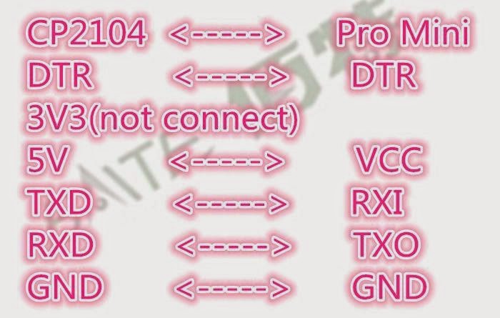
ผมค้นๆ มาดู มี chip บนบอร์ดแปลง USB to TTL หลายตัว และ แต่ละตัวก็มีวิธีการต่อที่แตกต่างกัน
 |
| Chip รหัส CP2104 |
 |
| Chip รหัส CH340 ที่ผมใช้อยู่ |
 |
| Chip รหัส CH340 ที่ผมใช้อยู่ และวิธีการต่อ |
 | |
| Chip รหัส CP2102 |
ตอนถัดไปจะเริ่มต่อ DHT11 และ LCD 16X2 และ NRF2401 Wireless Module บน Pro Mini ครับ